Complete list of parts needed to produce the 8bit-Hub.
| Item (number) | Identification |
| ATMega2560+ESP8266 (x1) | 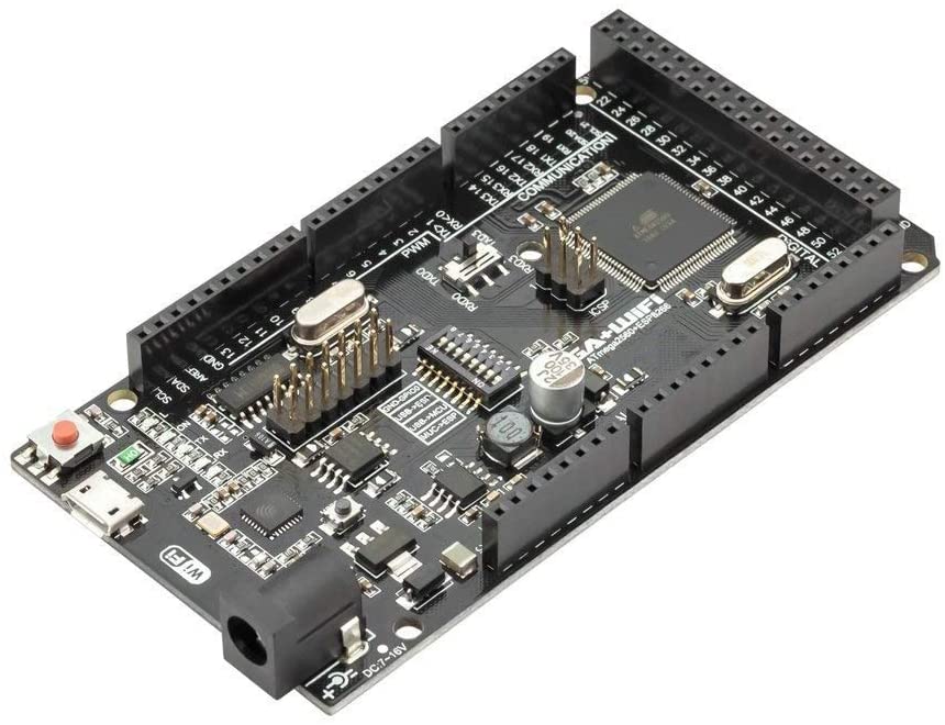 |
| LCD 20×4 I2C (x1) | 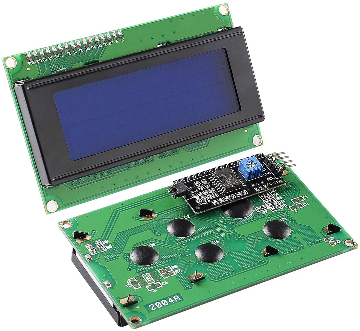 |
| MicroSD module (x1) | 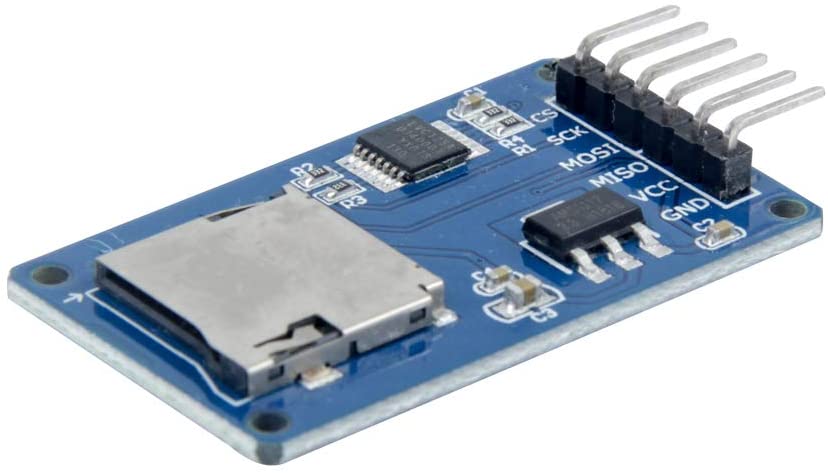 |
| PS2 socket module (x1) | 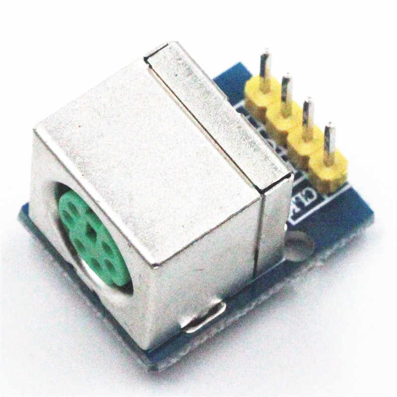 |
| Logic level converter (x1) | 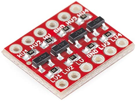 |
| DB9 male connector (x4) | 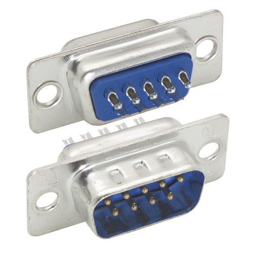 |
| DB9 female connector (x1) | 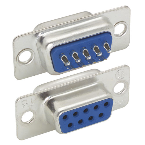 |
| DB9 shell (x1) | 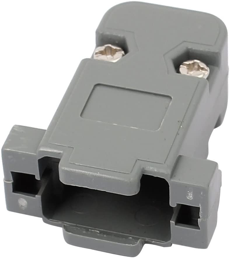 |
| 10cm jump wires (male/male x 35) (male/female x 16) (female/female x 2) | 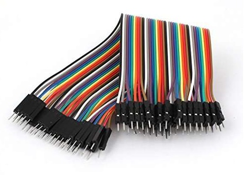 |
| 3D Printed Case | 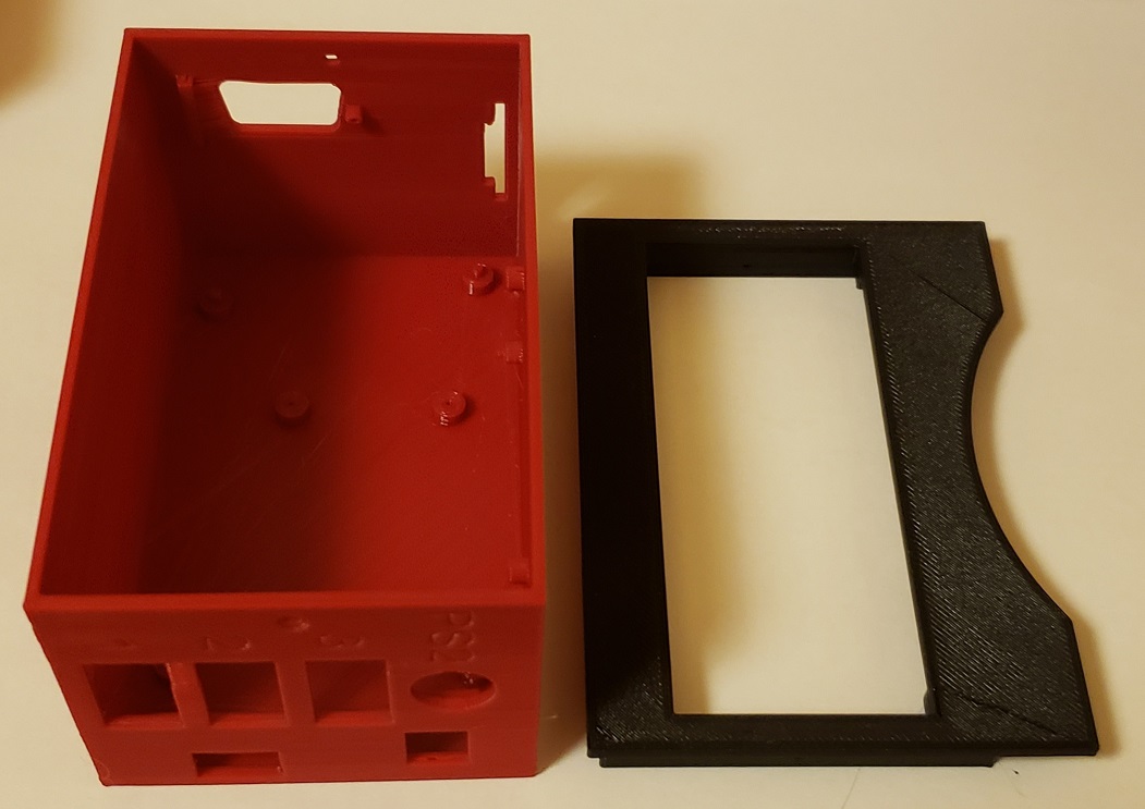 |
| Self-tapping screws M2.3×8 (x4) M2.0x7 (x2) M1.7×5 (x5) M1.7×3 (x4) | 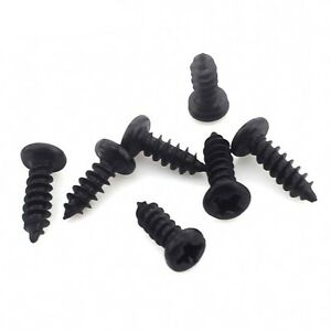 |
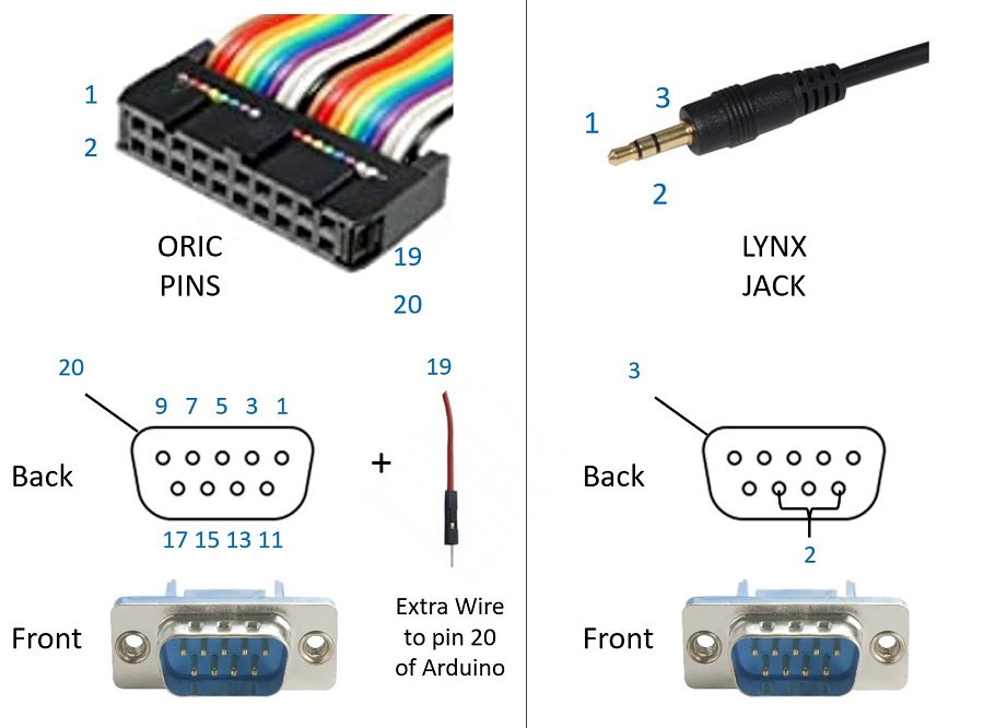
| (LYNX COM) 2m cable with 2.5 mm jack | 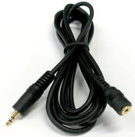 |
| (ORIC COM) 60cm flat ribbon cable with 20 pins | 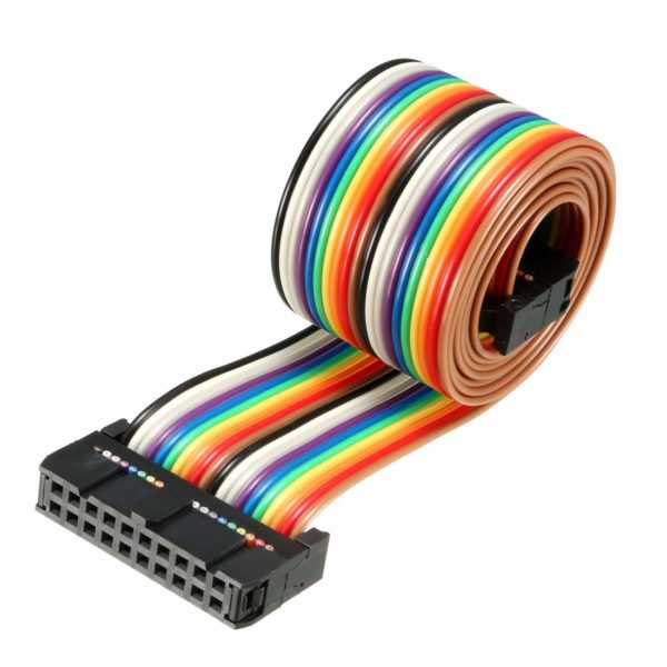 |
To produce a Hub takes 3-4 hours, the actual build steps are as follows:
- Jump wires are soldered to the DB9 connectors and logic converter.
- Logic converter is connected to PS2 socket module.
- LCD screen is attached to 3D printed front cover.
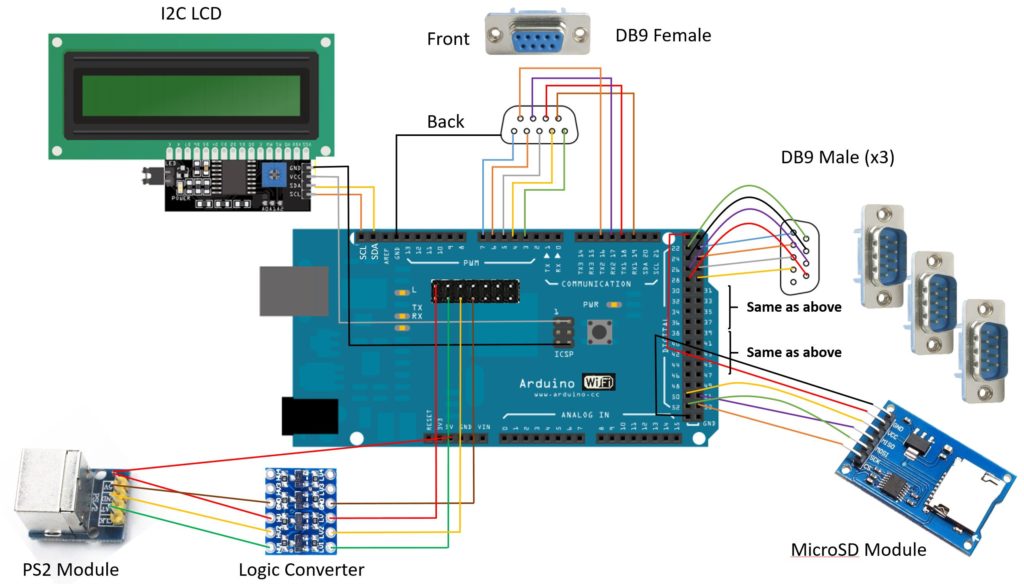
- Wires from all modules are connected to the main board.
- Main board is mounted inside the 3d printed case.
- Modules are attached to the side of case.
Finally, the communication cable is produced by cutting the COM cable and soldering to a male DB9 connector with protective shell.